Carbon filter: Difference between revisions
m (→Build steps:: Added coupling image) |
(Change instructions for new models) |
||
| Line 3: | Line 3: | ||
== 385 motor Fan (Beta) == |
== 385 motor Fan (Beta) == |
||
[[File:385 fan.png|thumb|267x267px]] |
[[File:385 fan.png|thumb|267x267px]] |
||
| ⚫ | |||
| ⚫ | |||
| ⚫ | |||
This fan is also compatible with the filter below |
This fan is also compatible with the filter below |
||
| Line 11: | Line 10: | ||
* 385 Motor |
* 385 Motor |
||
| − | * |
+ | * Case bottom (3D printed) |
| − | * |
+ | * Case top (3D printed) |
| − | * |
+ | * Case walls (3D printed) |
| + | * Install spacer (3D printed) |
||
| − | * [https://cannawiki.net/wiki/index.php/File:385_fan_blades.3mf Fan blades] (3D printed) |
||
| + | * Impeller (3D printed) |
||
| − | * [https://cannawiki.net/wiki/index.php/File:385_Motor_holder.3mf Motor holder] (3D printed) |
||
| + | * Motor holder (3D printed) |
||
| − | * 2.3mm to 5mm ridged shaft coupling |
||
| + | * 2.3mm grub screw prop adapter |
||
| − | * 5mm * 20mm thread rod (Or M5*20mm bolt with the head cut off) |
||
| − | * |
+ | * 7x M4 bolts |
| + | * 4x M4 nuts |
||
* 12v female barrel jack |
* 12v female barrel jack |
||
| Line 24: | Line 24: | ||
This will work best with a well-calibrated printer, this design includes a lot of press fits. Some parts may require sanding after printing to fit correctly. |
This will work best with a well-calibrated printer, this design includes a lot of press fits. Some parts may require sanding after printing to fit correctly. |
||
| − | 1. 3D Print all parts[[File:385 fan mid assembly.jpg|thumb]]2. Solder wires onto the 385 motor if it doesn't already have them. (Optionally on the other end solder a 12V barrel jack) |
||
| − | 3. Insert the motor all the way into the [https://cannawiki.net/wiki/index.php/File:385_Motor_holder.3mf Motor holder] and snap the motor holder into the case walls. It should be a press fit (Optionally add a dab of superglue to the bottom of the motor to help it stay in the motor holder. |
||
| + | 1. 3D Print all parts |
||
| ⚫ | |||
| + | 2. Solder wires onto the 385 motor if it doesn't already have them. |
||
| − | 1. Insert the 5mm * 20mm rod into the shaft coupling and tighten the grub screws to secure. Take care to keep the rod straight. |
||
| − | [[File:Shaft coupling with threaded rod.png|thumb|189x189px|Shaft coupling with threaded rod]] |
||
| − | 2. Add the [https://cannawiki.net/wiki/index.php/File:385_fan_blades.3mf Fan blades] onto the thread and tighten the M5 nut to secure them. |
||
| + | 3. Insert the motor all the way into the Motor holder. It will be a tight fit. Feed the wires through the case and bolt the motor holder into the case. Once attached feed the wires back into the case through the slit. |
||
| ⚫ | |||
| ⚫ | |||
| ⚫ | |||
| + | 1. On the side, put the prop adapter through the central hole of the impeller and tighten a nut on the other side. |
||
| − | 4. Cover with [https://cannawiki.net/wiki/index.php/File:385_case_top.3mf Case top]. This can be secured with tape so that the fan is easy to open up if needed |
||
| + | |||
| ⚫ | 2. Put the install spacer around the motor shaft. Then put the impeller onto the shaft on top of the spacer. The spacer will ensure there is clearance between the impeller and case floor. Tighten the grub screws of the prop adapter. This will require an M3 Allen key that is over 60mm long as you will have to reach under the impeller |
||
| + | |||
| + | 4. Cover with Case top. This should clip into place and may require some trimming if it does not fit initally |
||
| + | |||
| + | The fan can easily be mounted with heavy duty velcro, this makes for easy repairs |
||
== 120mm PC fan conversion kit == |
== 120mm PC fan conversion kit == |
||
Revision as of 21:30, 21 February 2024
Typically, in indoor grows, the smell produced by a flowering plant is undesirable to have outside of the growing environment, this has spurred the invention of filters utilizing activated carbon to absorb this odor.
385 motor Fan (Beta)

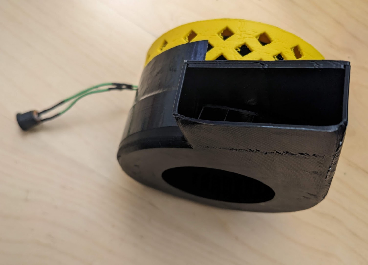
This is a centrifugal fan that can be 3D printed and is compatible with the Cannawiki grow controller. A motor driver such as the TB6612FNG is required so that it can be controlled. This fan is designed for the 385 motor to be driven at 12V, but most 385 motors can be run as low as 4.5v.
This fan is also compatible with the filter below
Parts
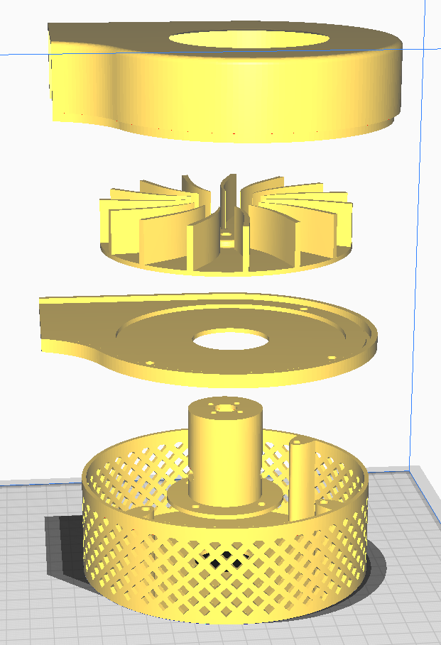
- 385 Motor
- Case bottom (3D printed)
- Case top (3D printed)
- Case walls (3D printed)
- Install spacer (3D printed)
- Impeller (3D printed)
- Motor holder (3D printed)
- 2.3mm grub screw prop adapter
- 7x M4 bolts
- 4x M4 nuts
- 12v female barrel jack
Build steps:
This will work best with a well-calibrated printer, this design includes a lot of press fits. Some parts may require sanding after printing to fit correctly.
1. 3D Print all parts
2. Solder wires onto the 385 motor if it doesn't already have them.
3. Insert the motor all the way into the Motor holder. It will be a tight fit. Feed the wires through the case and bolt the motor holder into the case. Once attached feed the wires back into the case through the slit.

4. Add the Case bottom on top of the case assembly so far. It should sit flat and be flush with the top of the motor holder. Screw in the 3 M4 bolts
1. On the side, put the prop adapter through the central hole of the impeller and tighten a nut on the other side.
2. Put the install spacer around the motor shaft. Then put the impeller onto the shaft on top of the spacer. The spacer will ensure there is clearance between the impeller and case floor. Tighten the grub screws of the prop adapter. This will require an M3 Allen key that is over 60mm long as you will have to reach under the impeller
4. Cover with Case top. This should clip into place and may require some trimming if it does not fit initally
The fan can easily be mounted with heavy duty velcro, this makes for easy repairs
120mm PC fan conversion kit


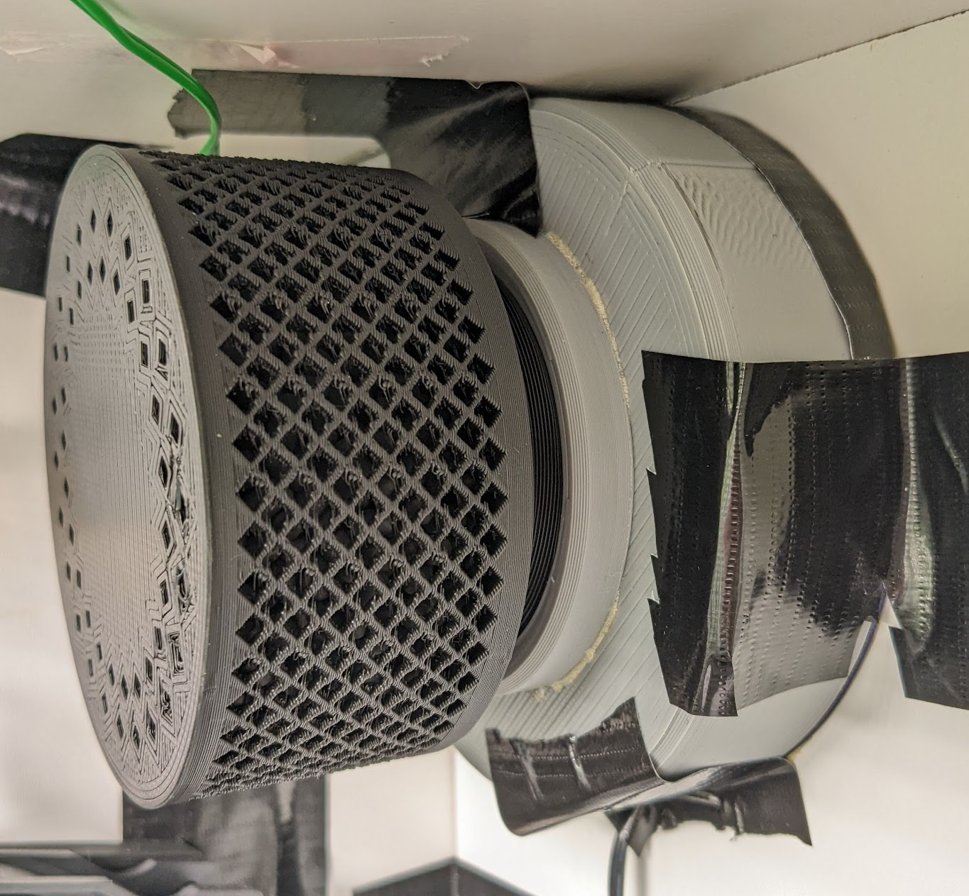
This fan is designed to be 3D printed and used as an exhaust fan with a filter using activated carbon pellets.
Steps
1. Take a standard 120mm PC case fan and remove the power cable from the frame of the fan. Cut the motor out of the frame with snips or a saw. Next, remove the fan blades from the fan hub. You may have to sand down the hub of the fan to remove the stubs of the fan blade.
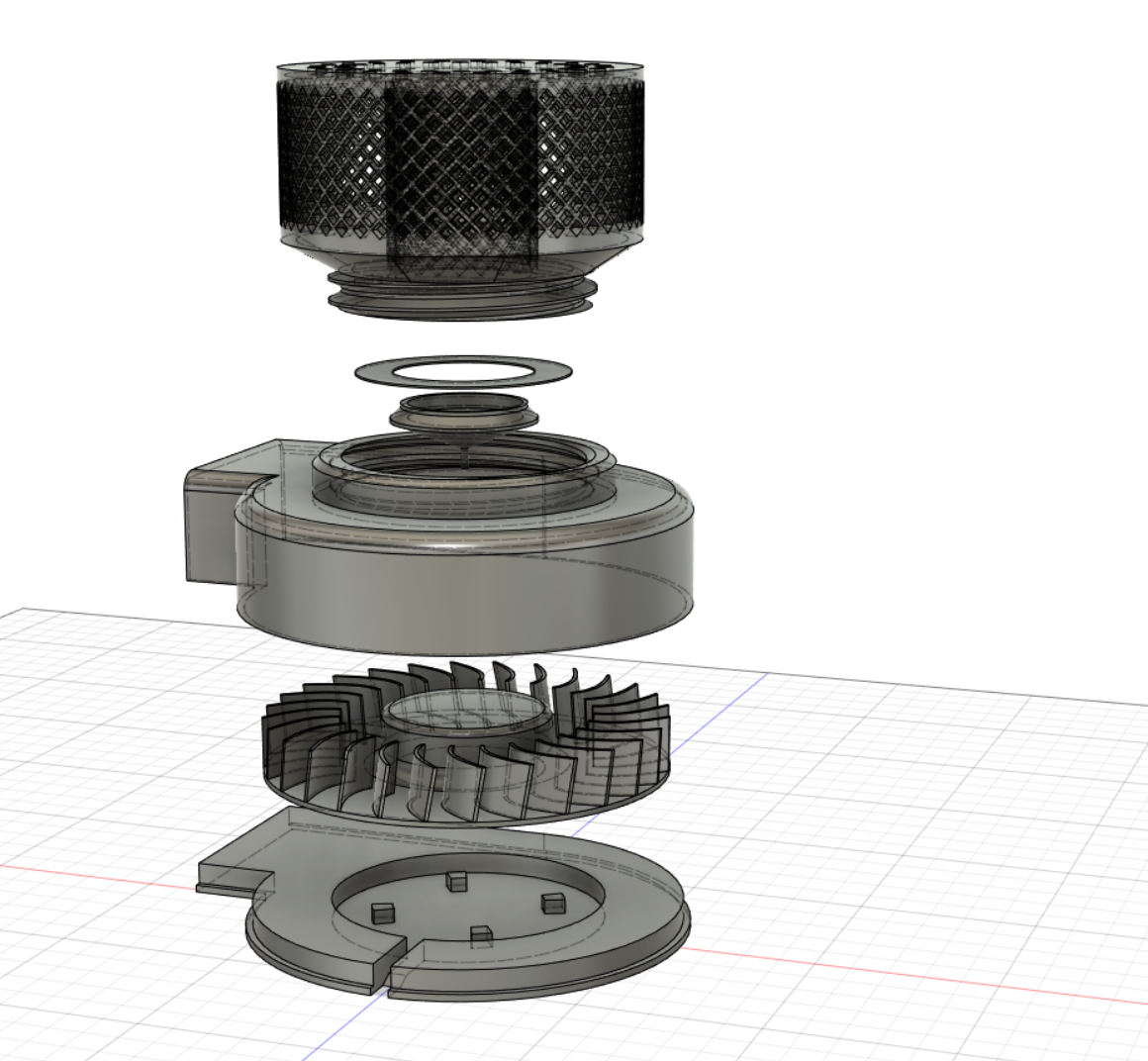
2. 3D print parts
- Filter chamber
- Filter chamber lid (print on 0.1 layer height)
- Filler tool (optional, to make filling the chamber easier)
- Screw thread
- Fan case top
- Fan blades
- Fan case bottom
3. Glue the screw thread to the case top model so that it aligns with the hole and leave it to dry.
4. Glue the motor from the fan in the center of the fan case bottom. The stubs around the center should help to line it up. The cable should exit the fan case from the bottom.
5. Glue or press fit the fan blades onto the hub. Make sure the old fan blades are really removed from the hub, sanding will help.
6. Place the case top onto the assembled fan and seal around the edges with tape.
7. To fill the filter chamber with carbon pellets place the filler tool in the cavity of the filter chamber. The filler tool is just there to stop the pellets from getting into the central cavity.
8. Remove the filler tool and put the chamber lid in the mouth of the filter chamber. It should be flexible enough to bend into place under the tabs on the inside of the screw.
9. Screw the filter chamber onto the fan body. Unscrew and replace the carbon pellets every 6 months or when the filter becomes ineffective.